之前写过一篇树莓派使用12864接口的2.3寸显示屏的文章,当时用的是并口,占用了太多的gpio资源,于是考虑使用spi接口的显示屏,最近的项目正好用到了spi接口的oled的显示屏,于是考虑把它用到树莓派上,先介绍下这款屏幕:0.96寸的oled屏,spi接口ssd1306主控芯片,在很多单片机上也可以用,它的优点是低功耗,以及它的分辨率很高,很难想象0.96寸上面有128*64的分辨率,而且0.96寸正好就是智能手表的尺寸啊,哈哈。本文使用python和c语言来完成功能。
个人原创,版权所有,转载请注明出处,并保留原文链接:
http://www.embbnux.com/2014/08/10/raspberry_use_spi_oled_screen_python_c/
一 首先介绍使用python来驱动这个spi接口的oled
(1) oled与树莓派连线
之前也介绍过使用python来操作树莓派的gpio口了,这回也一样不过是这次操作的是spi接口。
树莓派自带的26个排针接口里面就有一组spi接口:GPIO9(MISO) GPIO10(MOSI) GPIO11(SCL)
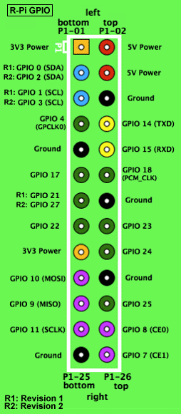
然后看一下我使用的oled的接口:

分别是GND VCC D0 D1 RST DC CS
各个口的功能与树莓派的io口连线分别如下:
GND接树莓派的GND, VCC接树莓派的3v3 POWER口,就是电源口,不要接到5V
CS是spi的片选口,可以多组spi同时使用,这里接树莓派的GPIO8(CE0)口,第24个管脚
DC口是数据与命令选择口,这里接到第13管脚,对于R1版本的树莓派就是GPIO21,我的是R2版本的,对应的是GPIO27
RST是复位口,这里接到GPIO17也就是11管脚
D1(MOSI)口,接到树莓派的GPIO10(MOSI)口,也就是21管脚
D0(SCLK)口,接到树莓派的GPIO11(SCLK)口,也就是23管脚
(2) 打开树莓派的spi口
树莓派默认的spi和i2c口都是被禁用的,使用之前必须先打开
首先是ssh登陆到树莓派上:
      vi /etc/modprobe.d/raspi-blacklist.conf

      #blacklist spi-bcm2708 #使用井号注释掉这行

  blacklist i2c-bcm2708  #如果要使用i2c就注释掉这行
保存后重启树莓派,sudo reboot,这样就会打开树莓派的spi口,具体你可以在/dev目录下看到两个文件:spidev0.0 spidev0.1,对应于gpio口上的spi口,0和1表示片选管脚ce0和ce1
(3) 使用python开始驱动spi口的oled
还是用ssh登陆到树莓派上:
#安装一些并要的软件,如果因为网络安装不成功,请重复该命令

sudo apt-get update
 sudo apt-get install build-essential python-dev python-pip
 sudo pip install RPi.GPIO
 sudo apt-get install python-imaging python-smbus
 sudo apt-get install git

#clone 下国外友人提供的python库
git clone https://github.com/adafruit/Adafruit_Python_SSD1306.git
cd Adafruit_Python_SSD1306
sudo python setup.py install
下面就可以使用python来驱动这个oled了:
新建个python文件:spioled.py
import time

import Adafruit_GPIO.SPI as SPI
import Adafruit_SSD1306

import Image
import ImageDraw
import ImageFont

# Raspberry Pi pin configuration:
RST = 17
# Note the following are only used with SPI:
DC = 27 #如果是r1版本的树莓派这里改为DC=21
SPI_PORT = 0
SPI_DEVICE = 0

# 128x64 display with hardware SPI:
disp = Adafruit_SSD1306.SSD1306_128_64(rst=RST, dc=DC, spi=SPI.SpiDev(SPI_PORT, SPI_DEVICE, max_speed_hz=8000000))

# Initialize library.
disp.begin()

# Clear display.
disp.clear()
disp.display()

# Create blank image for drawing.
# Make sure to create image with mode '1' for 1-bit color.
width = disp.width
height = disp.height
image = Image.new('1', (width, height))

# Get drawing object to draw on image.
draw = ImageDraw.Draw(image)

# Draw a black filled box to clear the image.
draw.rectangle((0,0,width,height), outline=0, fill=0)

# Draw some shapes.
# First define some constants to allow easy resizing of shapes.
padding = 2
shape_width = 20
top = padding
bottom = height-padding
# Move left to right keeping track of the current x position for drawing shapes.
x = padding
# Draw an ellipse.
draw.ellipse((x, top , x+shape_width, bottom), outline=255, fill=0)
x += shape_width+padding
# Draw a rectangle.
draw.rectangle((x, top, x+shape_width, bottom), outline=255, fill=0)
x += shape_width+padding
# Draw a triangle.
draw.polygon([(x, bottom), (x+shape_width/2, top), (x+shape_width, bottom)], outline=255, fill=0)
x += shape_width+padding
# Draw an X.
draw.line((x, bottom, x+shape_width, top), fill=255)
draw.line((x, top, x+shape_width, bottom), fill=255)
x += shape_width+padding

# Load default font.
font = ImageFont.load_default()

# Alternatively load a TTF font.
# Some other nice fonts to try: http://www.dafont.com/bitmap.php
#font = ImageFont.truetype('Minecraftia.ttf', 8)

# Write two lines of text.
draw.text((x, top),    'Hello',  font=font, fill=255)
draw.text((x, top+20), 'World!', font=font, fill=255)

# Display image.
disp.image(image)
disp.display()
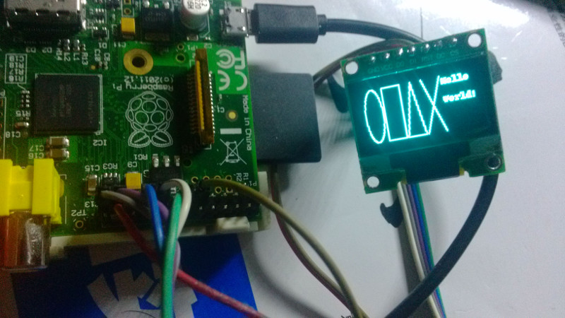
运行该程序,sudo python spioled.py
就会发现显示屏开始有显示了:
二 使用c语言来驱动这个spi接口的oled
树莓派是支持使用c语言来操作底层的gpio的,spi也可以,这里介绍使用c来使这个oled屏显示:
与树莓派的连线和上面的一样,这里就不介绍了.一样要打开spi口才可以使用
直接ssh登陆到树莓派 :
sudo apt-get update
sudo apt-get install vim
sudo apt-get install build-essential
sudo apt-get install cmake
sudo apt-get install git

git clone https://github.com/michaelKle/libssd1306.git
cd libssd1306

vim src/testSSD1306
int dcPin = 27; #如果是r1版本的,这里改为21,保存退出,:wq
编译该c语言包
mkdir build
cd build
cmake ..
make
测试:
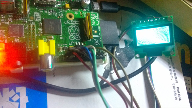
cd build/src
sudo ./testSSD1306
没遇到什么问题的话,这里应该可以显示了,会有一段动画:
就介绍到这里吧.
参考程序和文章:
https://learn.adafruit.com/ssd1306-oled-displays-with-raspberry-pi-and-beaglebone-black/
http://mrdevnotes.wordpress.com/2013/03/01/adafruit-oled-with-the-raspberry-pi/
缓存测试
请问,为什么,我根据你写的程序,出现的是花屏呢?
你线接错了吧
如果能接上三星手机的屏幕就好了.
> D1(MOSI)口,接到树莓派的GPIO10(MOSI)口,也就是21管脚
GPIO 10的MOSI应该是19吧?
感谢分享
您好,非常感谢您分享教程。请问为何我程序输出为花屏呢?
MOSI口,已接到树莓派的GPIO10(MOSI)口,也就是17管脚了。
请问树莓派40脚的怎么接线